Posts

Smart Blind stick Code

Code int trigpin = 4; int echopin = 5; int buzzer= 3; long duration; int distance; void setup() {   pinMode(3,OUTPUT);   pinMode(trigpin, OUTPUT);   pinMode(echopin, INPUT);    } void loop() {   digitalWrite(trigpin, LOW);   delayMicroseconds(2);   digitalWrite(trigpin, HIGH);   delayMicroseconds(10);   digitalWrite(trigpin, LOW);      duration = pulseIn(echopin, HIGH);   distance = duration*0.034/2;   Serial.print("Distance: ");   Serial.println(distance);      if(distance<30)   {     digitalWrite(3, HIGH);   }   else   {     digitalWrite(3, LOW);   } }

Arduino Interfacing With Ultrasonic Sensor (HC-SR04)

Image
Circuit Diagram :- Code:- const int trigPin = 4; const int echoPin = 5; long duration; int distance; void setup() {   pinMode(trigPin, OUTPUT);   pinMode(echoPin, INPUT);   Serial.begin(9600);    } void loop() {   digitalWrite(trigPin,LOW);   delayMicroseconds(1);   digitalWrite(trigPin,HIGH);   delayMicroseconds(20);   digitalWrite(trigPin,LOW);     // Reads the echopin, returns the sound wave travel time in microseconds  duration = pulseIn(echoPin,HIGH);  // Calculation of distance  distance = duration*0.034/2; //prints the distance on serial Monitor  Serial.print("Distance:"); Serial.println(distance); delay(500); }  

Electronic Dice Project

Image
Circuit Diagram :-

Cell Phone Detector Project For Students

Image
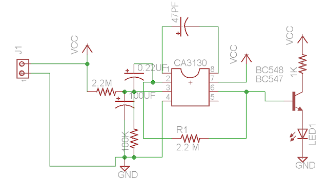
Circuit Diagram :- Circuit Layout :-  Components List :- 3x3 inch copper clad PCB - 1 Piece CA3130 IC - 1 Piece BC 548 Transistor - 1 Piece 5mm Led - 1 Piece 0.22uf capacitor - 1 Piece 100 uf capacitor - 1 piece 47 pf capacitor - 1 Piece 9v Battery with cap - 1 Piece 1x2 green terminal - 1 Piece 100 kilo ohm resistor - 1 Piece 2.2 Mega ohm resistor - 2 Piece 1 kilo ohm resistor - 1 Piece Working:- There is natural electromagnetic field around the capacitor caused by 50Hz electric wiring. When the mobile fan radiates high frequency radiation, capacitor oscillates and release energy in the inputs of IC. This oscillation is indicating by Flashing of LED.

Water Level Indiacator

Image
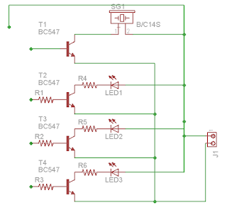
Components:- BC 547 Transistor - 4 Pieces 220 ohm Resistor - 6 Pieces Buzzer - 1 Piece 9v Battery With Cap - 1 Piece Glass Epoxy Copper Clad PCB  - 1 piece Jumper wires LED - 3 Pieces Plastic container - 1 Piece 1x2 Green connector - 1 Piece Circuit :- Layout :- Working:- This is a simple electronic project, In which we are using 4 BC547 transistors. Here R1, R2, R3 and Base of T1 is representing four levels of water and positive terminal of battery is going in water. When the water level will be reach at R3 then T4 transistor will be work as a switch and LED will be turn on. Same process will be repeat when water level will be reach at R2, R1, and Base of T1. LED's will be turn on at R2 and R1. T1 is a top level of tank and buzzer is connect with this point so when the water will be reach at the top level of tank then buzzer will be turn on.

Automatic Street Light Using Transistor

Image
Circuit Diagram :- Circuit Layout:- Components:- R1 = 1 k R2 = 1 k Jp1 = LDR T1 = BC547 R3 = 10 k R4 = 1 k LED 5 mm Working :- The LED in this project will be turn on during night and turn off during day. Generally a (LDR) Light Depending Resistor is using here to sense the presence of LIGHT. We cannot join LED directly to LDR. Several switching methods are must to make an LED to respond, when LDR is set aside at Dark or light then transistors will be work as a Switch. When LDR will be in light then LED will be OFF and when LDR will be in darkness at that time LED will be ON.

Musical doorbell project for students

Image
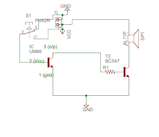
Components using in this projects are :- UM66 ic - 1 BC 547 - 1 Glass epoxy board - 1 Self lock switch - 1 1x2 Screw terminal - 1 Speaker - 1 100 ohm resistor - 1 9v battery + cap - 1 UM66T  is a melody IC. It is basically intended for use in Telephones, toys, bells etc. There is one inbuilt tone and a beat generator in this ic. The tone producer is a programmed separator which produces certain frequencies. These frequencies are a part of the oscillator frequency as well as the beat generator is also a programmed divider which includes 15 available beats. Four beats of these can be selected. When power is turned on, then melody begins from the first note as well as melody generator is reset. The external npn transistor which is connected to the output of UM66 can drive to speaker. There are so many versions of UM66T are available today which produce tone of different songs. For example, UM66T01 generates tone for songs ‘Jingle bells’, ‘Santa Clau...